This page deals with connecting 4 dip-switches or 1 hexadecimal coding switch to an AVR microcontroller (e.g. ATmega8) using only 1 wire. The basic idea is to create an analog voltage level using resistors, which can be digitalized again, using the internal A/D converter of the microcontroller. Even if this might sound quite easy, chosing the resistors is rather tricky, if you want to fulfill the following goals:
Using a computer simulation the following values turned out to be best (within reasonable orders of magnitude):
The absolute maximum tolerance for these values is ±1.135%. The circuit looks as follows:
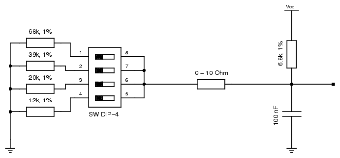
The 4 dip-switches can be replaced by a single hexadecimal coding switch. Note that the "0-10 Ohm" resistor is optional. It represents the resistance of a longer cable and/or plug connections. If the switches are connected with a longer cable, it might be advisable to add additional components to compensate radio interference, e.g. a second capacitor with 10 µF parallel to the 100 nF capacitor.
Many AVR controllers contain a 10 bit A/D converter with an absolute error of max. ±2/1024. As there is no additional tolerance margin in the calculations, you should use the ADC Noise Reduction Mode of the AVR microcontrollers, while measuring the voltage level. Given the tolerance of the used resistors, the nearest E24 resistors for the values of parallel connections of the resistors used for the switches, and also given the absolute error of the A/D converter you get the following mapping table for the output of the A/D converter:
| hex value | 12k | 20k | 39k | 68k | single resistor | output of A/D converter |
|---|---|---|---|---|---|---|
| 0x0 | open | open | open | open | ∞ | 1022-1023 |
| 0x1 | open | open | open | closed | 68k | 927-935 |
| 0x2 | open | open | closed | open | 39k | 867-877 |
| 0x3 | open | open | closed | closed | 24k | 792-810 |
| 0x4 | open | closed | open | open | 20k | 758-771 |
| 0x5 | open | closed | open | closed | 15k | 698-718 |
| 0x6 | open | closed | closed | open | 13k | 665-684 |
| ! 0x8 ! | closed | open | open | open | 12k | 646-661 |
| ! 0x7 ! | open | closed | closed | closed | 11k | 625-642 |
| 0x9 | closed | open | open | closed | 10k | 602-622 |
| 0xA | closed | open | closed | open | 9.1k | 578-596 |
| 0xB | closed | open | closed | closed | 8.2k | 548-568 |
| 0xC | closed | closed | open | open | 7.5k | 529-545 |
| 0xD | closed | closed | open | closed | 6.8k | 502-520 |
| 0xE | closed | closed | closed | open | 6.2k | 481-500 |
| 0xF | closed | closed | closed | closed | 5.6k | 455-478 |
Note that the parallel circuit of 20k, 39k and 68k (hex-value 0x07) results in approx. 11k, which is smaller than the single 12k resistor. Therefore the hex-values 0x7 and 0x8 have a swapped position in the table. Using the unused spaces in the output values of the A/D converter, you can detect more values using single resistors, which have no representation in the hex-/dip-switches:
| hex value | 12k | 20k | 39k | 68k | single resistor | output of A/D converter |
|---|---|---|---|---|---|---|
| 0x0 | open | open | open | open | ∞ | 1022-1023 |
| 0x1 | open | open | open | closed | 68k | 927-935 |
| 56k | 909-917 | |||||
| 47k | 890-899 | |||||
| 0x2 | open | open | closed | open | 39k | 867-877 |
| 33k | 844-854 | |||||
| 30k | 829-840 | |||||
| 27k | 812-824 | |||||
| 0x3 | open | open | closed | closed | 24k | 792-810 |
| 22k | 776-788 | |||||
| 0x4 | open | closed | open | open | 20k | 758-771 |
| 18k | 737-750 | |||||
| 0x5 | open | closed | open | closed | 15k | 698-718 |
| 0x6 | open | closed | closed | open | 13k | 665-684 |
| ! 0x8 ! | closed | open | open | open | 12k | 646-661 |
| ! 0x7 ! | open | closed | closed | closed | 11k | 625-642 |
| 0x9 | closed | open | open | closed | 10k | 602-622 |
| 0xA | closed | open | closed | open | 9.1k | 578-596 |
| 0xB | closed | open | closed | closed | 8.2k | 548-568 |
| 0xC | closed | closed | open | open | 7.5k | 529-545 |
| 0xD | closed | closed | open | closed | 6.8k | 502-520 |
| 0xE | closed | closed | closed | open | 6.2k | 481-500 |
| 0xF | closed | closed | closed | closed | 5.6k | 455-478 |
| 5.1k | 431-447 | |||||
| 4.7k | 411-427 | |||||
| 3.9k | 389-405 | |||||
| 3.6k | 347-362 | |||||
| 3.3k | 327-342 | |||||
| 3.0k | 307-321 | |||||
| 2.7k | 284-299 | |||||
| 2.4k | 261-274 | |||||
| 2.2k | 244-258 | |||||
| 2.0k | 227-240 | |||||
| 1.8k | 208-221 | |||||
| 1.5k | 180-192 | |||||
| 1.2k | 149-160 | |||||
| 1k | 127-137 | |||||
| 820 | 106-116 | |||||
| 680 | 89-98 | |||||
| 560 | 74-83 | |||||
| 470 | 63-71 | |||||
| 390 | 52-60 | |||||
| 300 | 40-48 | |||||
| 220 | 29-36 | |||||
| 150 | 20-26 | |||||
| 91 | 11-17 |
If you can't use the ADC Noise Reduction Mode or if you need additional margin, you should consider using a pull-up resistor with 0.1% tolerance instead of 1% tolerance.
You may freely copy, modify, merge or use this data collection. I do not assure that the data is correct. Use at your own risk.
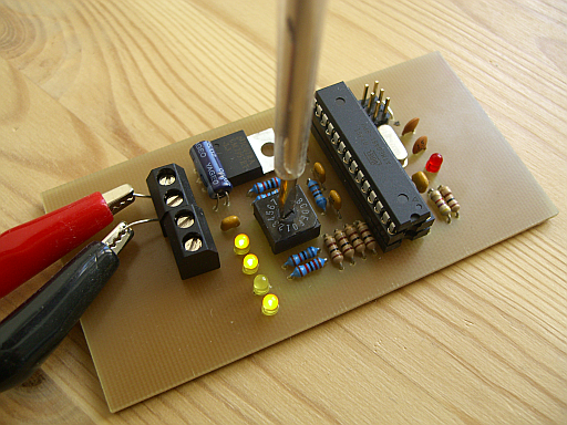
My test circuit worked as expected and looks as follows: